Custom stair designs.
I've been in the construction trades for close to 40 years now and have had many
opportunities to work on special projects. You can see a few of them following this link. In the early 80s I became
interested in spiral stairs and have been occasionally working with them ever since.
Perhaps 15 years ago I got interested in computers and eventually began using them in
stair design. The images below are just a sampling of some of the projects Computer Aided
Design, CAD, has helped create.
Several of the projects below were designed for other builders, several were made
to help visualize details. I do custom stair design and fabrication if it's called for,
but designing for others is also offered. If you have a special situation and you see the
benefits of building first with a computer gathering details, please let me know if I can
be of assistance. My rates are very reasonable as I like working with stairs and
CAD.
Click on the small pictures to bring up bigger ones.
|
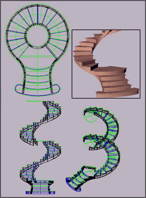
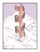
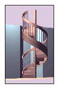
 A lady from down south sent me a photograph of a two story winding
staircase she was considering duplicating for a home she was building. I used my program
and her measurements to develop working drawings she could present to her builder. I'm
not sure who put the skids on her project, but as far as I know it was never built. I'd
think the costs were going to go through the roof.
A lady from down south sent me a photograph of a two story winding
staircase she was considering duplicating for a home she was building. I used my program
and her measurements to develop working drawings she could present to her builder. I'm
not sure who put the skids on her project, but as far as I know it was never built. I'd
think the costs were going to go through the roof. |
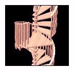
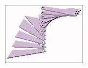
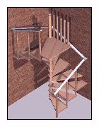
 I sent her detailed and dimensioned renderings of the main parts so she
could gather building estimates. Both flights were intended to be free standing, no
underneath supports. She would have been able to take the renderings to a wood shop and
priced materials as well as labor, not a minor benefit of CAD.
I sent her detailed and dimensioned renderings of the main parts so she
could gather building estimates. Both flights were intended to be free standing, no
underneath supports. She would have been able to take the renderings to a wood shop and
priced materials as well as labor, not a minor benefit of CAD. |
 These next two drawings were for two different buildings but similar
winding stairs were needed for each.
These next two drawings were for two different buildings but similar
winding stairs were needed for each. |
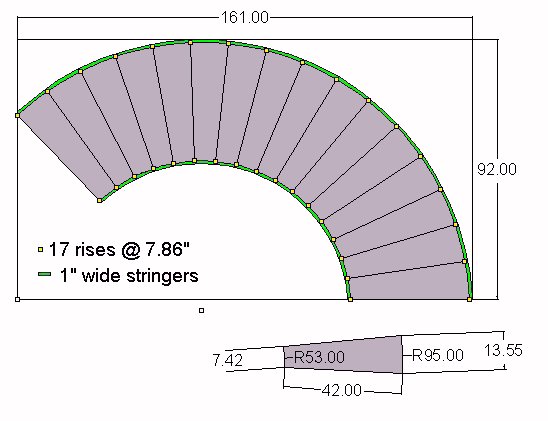
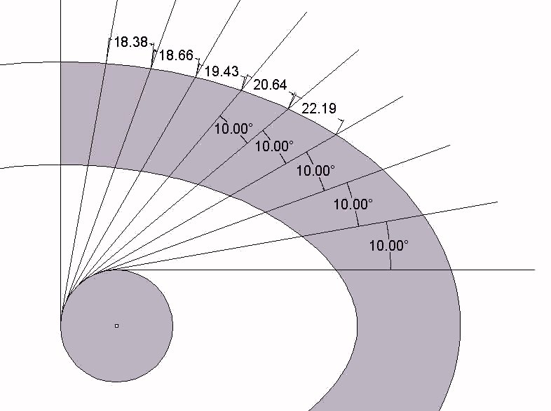
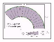
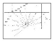
 The architect wanted to know exactly the results of tread shapes by using
constant radius stringers, or taking tread shapes using eliptical stringers. With CAD
it's common to use actual dimensions when designing, as seen here with 10" tread width
where the users feet would actually be stepping.
The architect wanted to know exactly the results of tread shapes by using
constant radius stringers, or taking tread shapes using eliptical stringers. With CAD
it's common to use actual dimensions when designing, as seen here with 10" tread width
where the users feet would actually be stepping. |
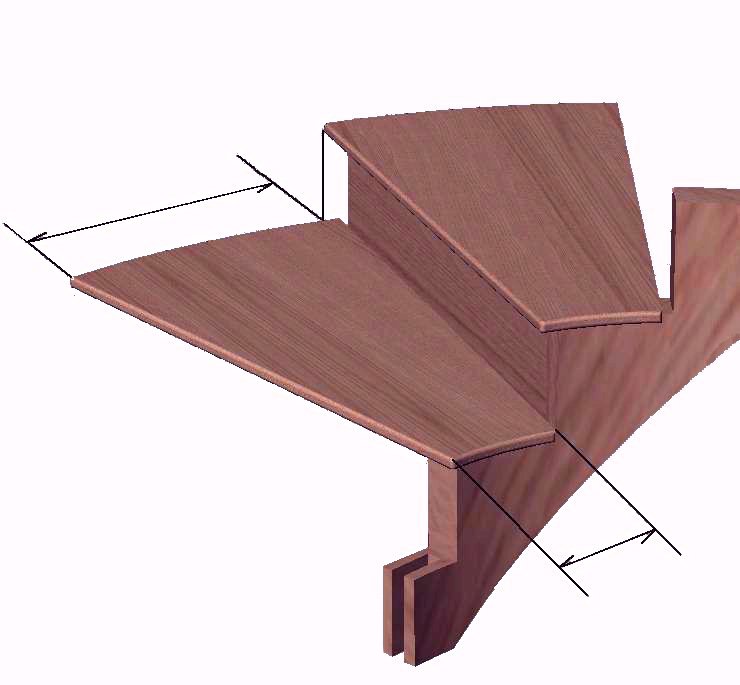
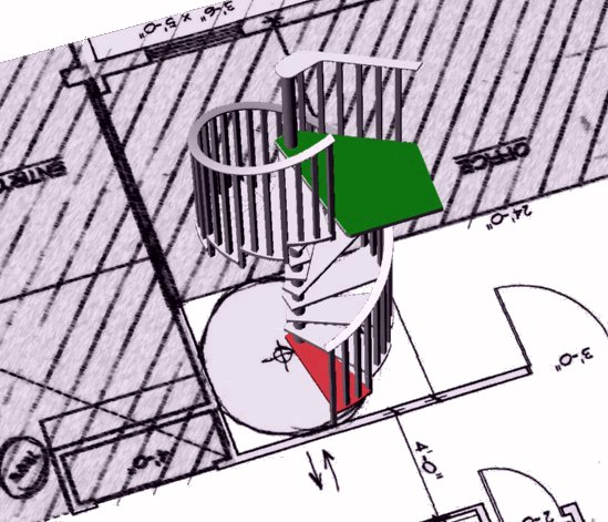
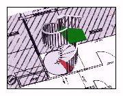 Every now and then I'll place one of my CAD models on a submitted print so
the owner of the project can see how the landing could work. This picture shows a green
landing and a red first step. If I remember right, this man wanted to make sure he could
fit between the wall corner and the start of the handrail.
Every now and then I'll place one of my CAD models on a submitted print so
the owner of the project can see how the landing could work. This picture shows a green
landing and a red first step. If I remember right, this man wanted to make sure he could
fit between the wall corner and the start of the handrail. |
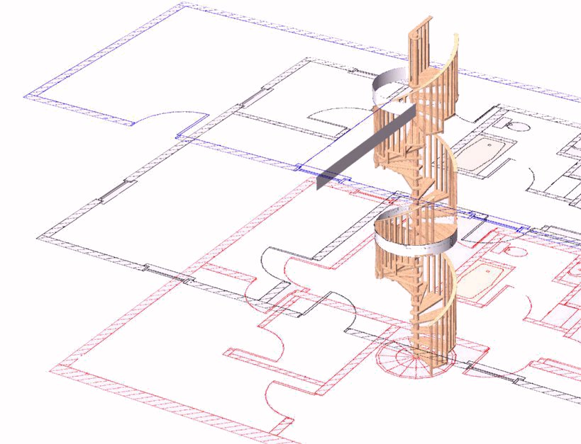
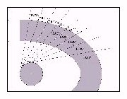
 In this one we're making sure the intermediate landing as well as the top
one ended where they should. Spirals aren't easy to visualize, especially if you haven't
done a few or lived with one for a while.
In this one we're making sure the intermediate landing as well as the top
one ended where they should. Spirals aren't easy to visualize, especially if you haven't
done a few or lived with one for a while. |
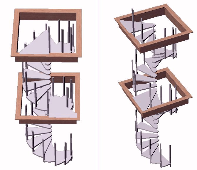
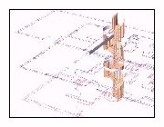
 Another stacked set of spirals where we were ckecking landing
positions.
Another stacked set of spirals where we were ckecking landing
positions. |
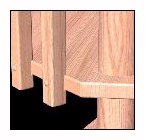
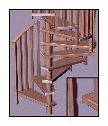
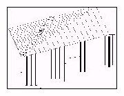
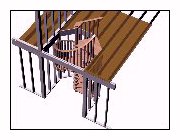 I built this stair for a builder friend of mine but we first had to show
the owner of the house where the bottom step and landing would be. He also had a concern
about mounting the landing so I detailed some of the framing around there. The second
floor is really a corner opposite the landing but I left it out for clarity.
I built this stair for a builder friend of mine but we first had to show
the owner of the house where the bottom step and landing would be. He also had a concern
about mounting the landing so I detailed some of the framing around there. The second
floor is really a corner opposite the landing but I left it out for clarity. |
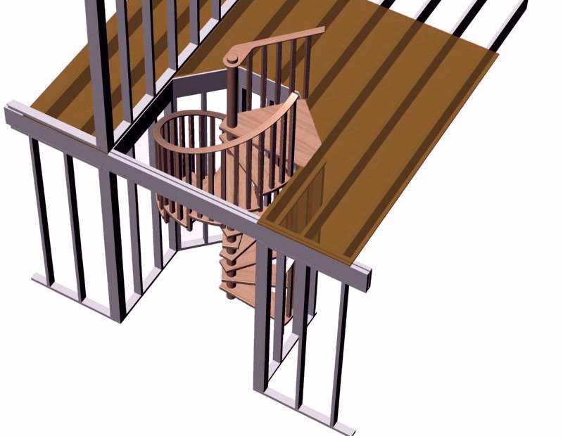
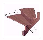
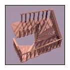
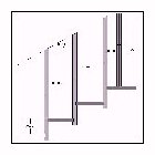
 This is an example on how I prefer to mount landings, notched down into the
loft edge.
This is an example on how I prefer to mount landings, notched down into the
loft edge. |
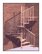
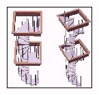 I also built this set of stacked spirals and took a trip to southern Ohio
to install it. I totally made both spirals in CAD, fabricated the parts, then went there
and installed them. Without the preliminary CAD work, I doubt the landing would have
mounted exactly where they needed to be. You can see more on this stair using this link.
I also built this set of stacked spirals and took a trip to southern Ohio
to install it. I totally made both spirals in CAD, fabricated the parts, then went there
and installed them. Without the preliminary CAD work, I doubt the landing would have
mounted exactly where they needed to be. You can see more on this stair using this link. |
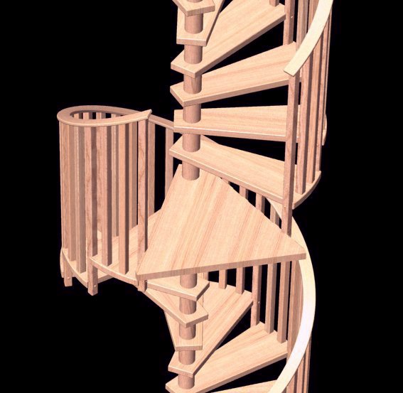
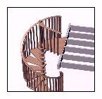
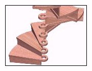
 I've done very little with solid winder stringers, but this spiral was
suggested as a project I might be interested in building. You can see construction
photographs following this
link.
I've done very little with solid winder stringers, but this spiral was
suggested as a project I might be interested in building. You can see construction
photographs following this
link. |
 It would be hard to beat having CAD models when you need views of details
normal drafting just couldn't accomplish in a reasonable time frame.
It would be hard to beat having CAD models when you need views of details
normal drafting just couldn't accomplish in a reasonable time frame. |
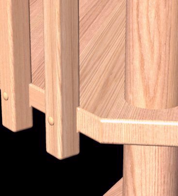
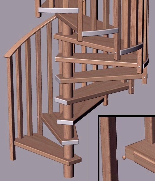
 Zooming in on specifics helps considerably in resolving misunderstandings.
Of interest here was why the back edge of landings aren't routed until the baluster
installation was determined.
Zooming in on specifics helps considerably in resolving misunderstandings.
Of interest here was why the back edge of landings aren't routed until the baluster
installation was determined. |
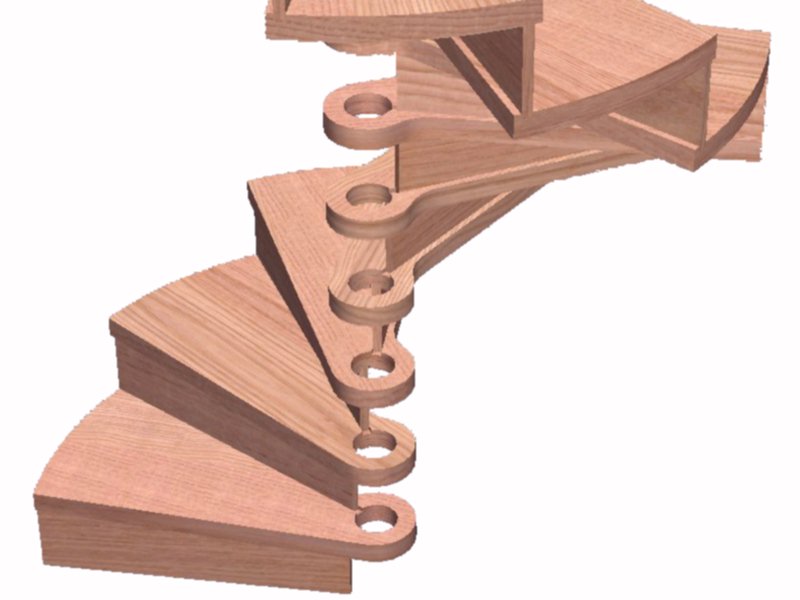
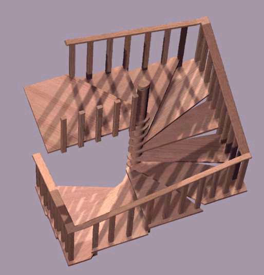
 Models can have any of their parts temporarily hidden from view. In this
view the center pole is removed as an obstruction to riser fabrication details.
Models can have any of their parts temporarily hidden from view. In this
view the center pole is removed as an obstruction to riser fabrication details. |
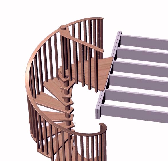
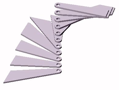
 As is easily seen here, revolving less than a full revolution makes narrow
treads.
As is easily seen here, revolving less than a full revolution makes narrow
treads. |
 Baluster mounts are more easily shown than described in writing. I often
use selected views of my models to show relationships in construction.
Baluster mounts are more easily shown than described in writing. I often
use selected views of my models to show relationships in construction. |
 I don't normally add lighting in CAD renderings as it's mostly
cosmetics.
I don't normally add lighting in CAD renderings as it's mostly
cosmetics. |
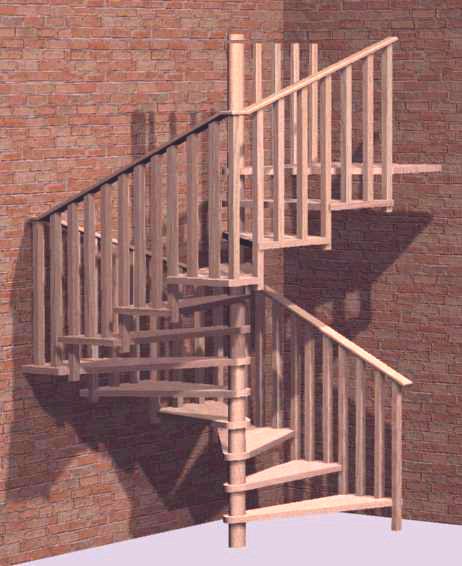
 Lighting does add realism and quite often makes the difference in asthetic
onsiderations.
Lighting does add realism and quite often makes the difference in asthetic
onsiderations. |
 Handrail development.
 |
 Tread layouts.
 |
 Dimensioning for handrail mounting screw locations.
 |
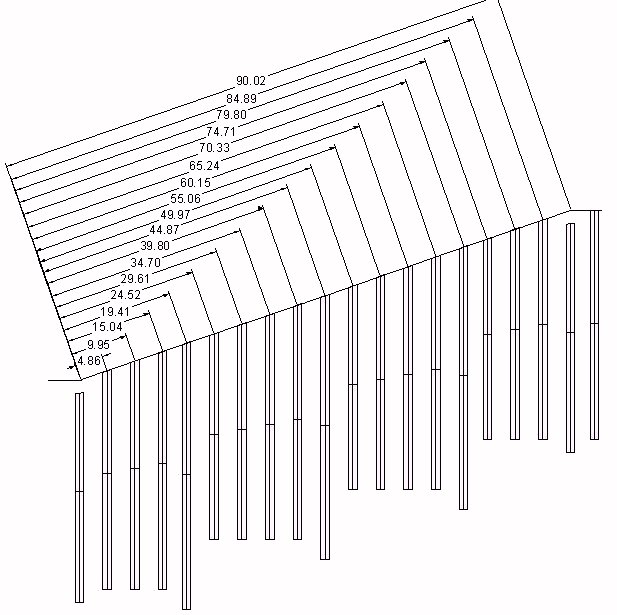
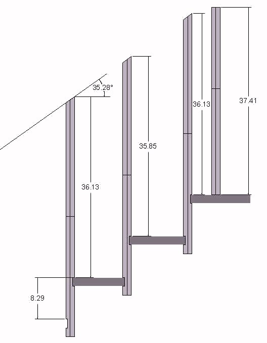
 Main baluster lengths.
 |
 Baluster mounting locations.
 |
|
Contact me through this link. jim@jself.com
|